Open Source Fighter
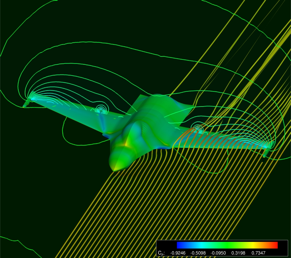 |
| Open Source Fighter Flowfield at M0.85, Aoa2.12o |
The Open Source Fighter configuration, results from the efforts of trying to build a realistic size aeroelastic test case. The geometry is based on publicly available data for the F-16. The F-16 has a documented history of exhibiting LCOs for certain configurations at specific flight conditions. This prompt a significant research effort using this configuration.
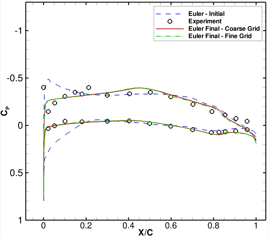
Based on published data, the wing geometry was modified to produce similar aerodynamic characteristics to the F-16 (see figures 3 and 4). A structural model was also developed under the same approach: using finite model updating techniques and publicly available data from GVT, it was possible to construct a finite element model resembling specific natural frequencies.
Further details on the files available here are described in the following document (guide to files)
CFD Resources
MSC.Nastran Resources
Solver Input Files
MSC.Nastran & CFD Results
 |
 |
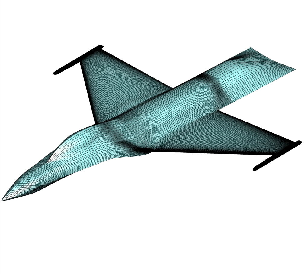
| Fig. 1: CFD Fine Grid |
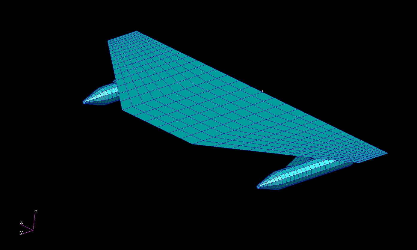
Fig. 2: MSC. Nastran Structural Model |
 |
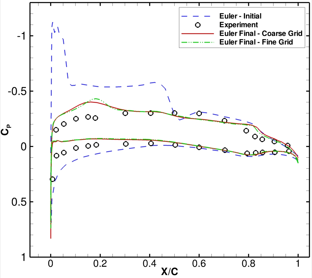 |
Fig. 3: CP at 59%Span
Comparison with F-16 |
Fig. 4: CP at 85%Span
Comparison with F-16 |
| |
Mode 1 |
Mode 2 |
Mode 3 |
Mode 4 |
| Updated FE model |
3.74h1 |
5.91p1 |
8.12y1 |
11.0hp |
| GVT |
4.07h1 |
5.35p1 |
8.12y1 |
12.25h2 |
hi - ith bending; p1 - pitch + torsion; y1 - yaw; hp - bending + pitch
Table 1: Results from structural finite element model updating
 |
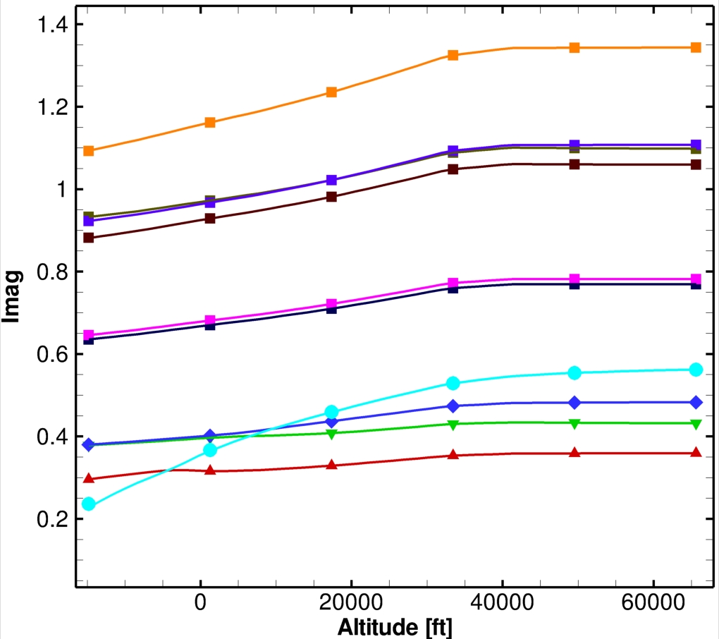 |
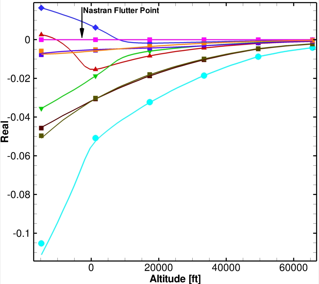
Fig. 5: CFD Based Damping Plot
(ASCII Data)
|
Fig. 6: CFD Based Frequency Plot |
Variability Study
For the Open Source Fighter, six parameters were used to represent the structural variability. Due to the size of the model, MC analysis is not viable; instead interval analysis was main tool to study the impact of variability on the onset of flutter. The structural model is made up of the fuselage and three regions along the wing span: root, middle (pylon) and tip; all these components have specific material characteristics, obtained from the finite element model updating procedure. To decrease the total number of parameters used in the variability study, a sensitivity analysis was performed and the following parameters were found to have the most significant impact on the onset of flutter:
| Parameter |
Nominal Value |
Allowed Variation |
| Store Spring Coefficient |
2x10⁶ |
+/-15% |
| Young's Modulus - Root |
157.3 GPa |
+/-10% |
| Young's Modulus - Middle |
96.7 GPa |
+/-10% |
| Material Density - Root |
5680 kg/m3 |
+/-10% |
| Material Density - Middle |
3780 kg/m3 |
+/-10% |
| Material Density - Tip |
3780 kg/m3 |
+/-10% |
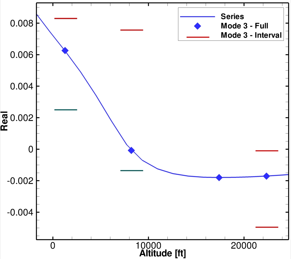 |
Fig. 6: Open Source Fighter CFD Based Interval Analysis -
Real Eigenvalue |
References
- S. Marques, H. Kodaparast, K. Badcock, J. Mottershead, Transonic Flutter Predictions for a Generic Fighter Configuration, Proceedings of the International Workshop on Fluid-Structure Interaction, Kassel University Press, Germany, 2009
- S. Marques, H. Kodaparast, K. Badcock, J. Mottershead, CFD Based Aeroelastic Stability Predictions Under the Influence of Structural Variability, 50th Structural Dynamics and Materials Conference, Palm Springs, California, 2009.
|