Isogai wing section model
The "typical section" aerofoil of Isogai (1979,1981) using the NACA 64A010 aerofoil at zero mean angle of attack is a numerical benchmark case for methods predicting aeroelastic instabilities. This two degree-of-freedom model with oscillating motions in pitch &alpha and plunge h is idealized as a point mass defining the centre of gravity, as well as a torsional and a translational spring attached to the elastic centre located a distance x&alpha away from the centre of gravity. The dimensionless structural parameters of this configuration were chosen to represent the dynamics of an outer section of a swept-back wing, and are summarized as follows (with c denoting the chord length and b as the semichord); centre of gravity at xcg/c=0.4 with off-set to centre of rotation x&alpha/b=-1.8 placing the pivotal point ahead of aerofoil leading edge, radius of gyration about pivotal point r&alpha/b=1.865, ratio of natural (uncoupled) frequencies &omegah/&omega&alpha=1.0, and aerofoil-to-fluid-mass ratio &mus=60. No structural damping is considered. A detailed description of the structural model can be found in Badcock et al (2004). A C-function to evaluate the structural residual is provided here.
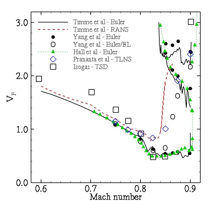
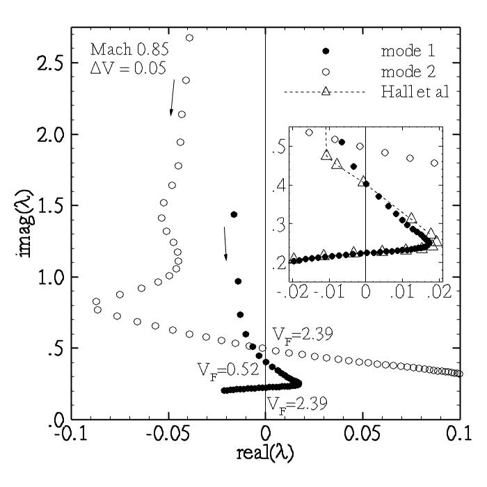
Figure 1 shows a comparison between results from different numerical methods illustrating the instability boundary as critical flutter speed index VF versus freestream Mach number. The s-shape of the curve in the deep transonic region, giving a second stable branch for higher values of the flutter speed index, is distinct for the inviscid aerodynamic modelling approaches. The mode tracing is visualized in Fig. 2 showing the migration of the eigenvalues corresponding to the two dominant aeroelastic modes originating in the wind-off structural modes. At fixed Mach number of Mach 0.85 the s-shaped appearance of the instability boundary is described. The inlay of the figure presents the migration of the eigenvalue of the first mode compared to results of the mode tracing done by Hall et al (2000) using a reduced order model based on a proper orthogonal decomposition technique. The behaviour with multiple critical flutter speed indices disappears for flow models considering viscous flow effects (using a chord Reynolds number of 6 million) such as RANS, thin-layer Navier-Stokes (TLNS) or integral boundary layer (BL) modelling.
|
|
|
Figure 1. Critical flutter speed index
data file |
|
Figure 2. Mode tracing at Mach 0.85
data file |
CFD Resources
(* - Input format of the University of Liverpool research codes)
References
- Badcock, K. J., Woodgate, M. A., and Richards, B. E., "Hopf bifurcation calculations for a symmetric airfoil in transonic flow", AIAA Journal, Vol. 42, No. 5, 2004, pp. 883-892.
- Hall, K. C., Thomas, J. P., and Dowell, E. H., "Proper orthogonal decomposition technique for transonic unsteady aerodynamic flows", AIAA Journal, Vol. 38, No. 10, 2000, pp. 1853-1862.
- Isogai, K., "On the transonic-dip mechanism of flutter of a sweptback wing", AIAA Journal, Vol. 17, No. 7, 1979, pp. 793-795.
- Isogai, K., "Transonic-dip mechanism of flutter of a sweptback wing: part II", AIAA Journal, Vol. 19, No. 9, 1981, pp. 1240-1242.
- Prananta, B. B., Hounjet, M. H. L., and Zwaan, R. J., "Two-dimensional transonic aeroelastic analysis using thin-layer Navier-Stokes method", Journal of Fluids and Structures, Vol. 12, 1998, pp. 655-676.
- Timme, S., and Badcock, K. J., "Searching for transonic aeroelastic instability using an aerodynamic model hierarchy", Tech. Rep. Deliverable D2.3, University of Liverpool, UK, 2009.
- Yang, S., Zhang, Z., Liu, F., Luo, S., Tsai, H.-M., and Schuster, D. M., "Time-domain aeroelastic simulation by a coupled Euler and integral boundary-layer method", AIAA Paper 2004-5377, 2004.
Contact
Sebastian Timme
|